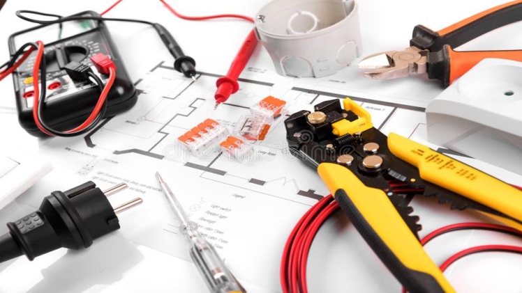
Circuit diagrams are the graphical representations of electrical circuits. These include electrical diagrams, wiring diagrams, electronic schematic diagrams, elementary diagrams, etc. A pictorial circuit diagram has simple component images, while a schematic one shows the interconnections and components of the circuit using standardised symbolic notations. The representation of the interconnections between different components in the schematic diagrams is different from the real arrangement of the physical device.
Apart from layout diagrams or block diagrams, circuit diagrams show real electrical connections. A figure meant to show the physical orientation of the wires and the elements or components they link is known as a layout or artwork, wiring diagram, or physical design. A circuit diagram is used for the circuit design, construction, and maintenance of electronic and electrical components. In digital circuits, circuit images are very useful when visualising expressions employing Boolean algebra.
Common Components of Circuit Diagram
An electric cell is the source of current. In its symbolic representation, the smaller terminal is negative, whereas the larger terminal is positive. A switch is a plug key that is used to stop or allow the movement of current upon pressing. It can be a closed or open switch. Wire joints are electrical wire connectors or ways that are helpful to link multiple wires together. This is represented by drawing a blob symbol at the point of connectivity. A battery is a combination of smaller cells, and its application is exactly the same as an individual cell. Wires crossing without joining are the wires that do not link; each one is represented without the blob symbols.
An electric bulb is an electrical device that utilises electricity to illuminate or glow. A resistor is used to restrict the amount of flow of current in the electrical circuit. A variable resistor is used to control the quantity of current flow by decreasing or increasing the resistance against the flow of current. It is also called the rheostat. A voltmeter is a device that measures the voltage across two points in an electric circuit. An ammeter is used to measure the electrical current flowing at a particular point.
In the past, circuit diagram symbols have varied from one country to another and have changed many times. However, now to an extent, most of the symbols are globally standardised. Basic circuit elements often have symbols pointing to represent some characteristic of the physical construction of the apparatus. For example, the resistor symbol dates back to the period when the circuit element was constructed from a long wire wrapped in such a way as not to generate inductance, which would have made the piece of wire into a coil. Now, such wire-wound resistors are used only in large-power functions, and smaller resistors are cast from carbon composition (carbon and filler mixture) or made as an insulating chip or tube coated with metal films. The standardised symbol of a resistor is now simplified to an oblong symbol, at times, with an ohms value embedded inside (in some cases, a zig-zag symbol is also used). An unusual circuit symbol is a series of peaks on one side of the line denoting the conductor instead of back-and-forth.
Types of Electrical Circuit Diagrams
Schematic Diagrams
The schematic diagram (ladder diagram) is considered to be the simplest type of electrical circuit diagram. This representation shows the electrical elements on horizontal lines without considering their physical position. It is primarily employed for troubleshooting, as it is very simple to analyse the functioning of the circuit. The loads are positioned on the extreme right of the diagram. The controls for every load are positioned to the left. To better understand the operation sequence, the diagram is read from the top left corner and then left to the right side, and from top to bottom side.
Pictorial Diagrams
A pictorial diagram denotes the electrical circuit elements in more detail, just like what they look like physically, and shows how the wiring is connected. Such diagrams can be employed to locate a particular component in a complicated system. It represents a sketch or a picture of the different components of a particular system and the wiring between the components. Such a simplified diagram allows one to instantly identify a system’s components, even if one is familiar with the physical appearance of the components. This circuit diagram represents the different electrical components irrespective of their physical position, how the wiring is denoted, or how the wiring is routed. However, it shows the sequence in which circuit components are attached.
Block Diagrams
The block diagram is used to show the sequence or order of circuit operations. These diagrams present functional descriptions, pointing out which components should operate first to get the desired output. They do not show specifics like component symbols or wire connections.
Wiring Diagrams
A wiring diagram is a simplified pictorial representation of a circuit. It represents the elements of the circuit as simplified shapes and signal connections between the different devices. The wiring diagram is the relative layout of the electrical circuit elements using the correct electrical symbols and wire connections. Even though a wiring diagram is the simplest to use for wiring a circuit installation, it is sometimes challenging to analyse the circuit function and could be better for troubleshooting

